Introduction To Hardware
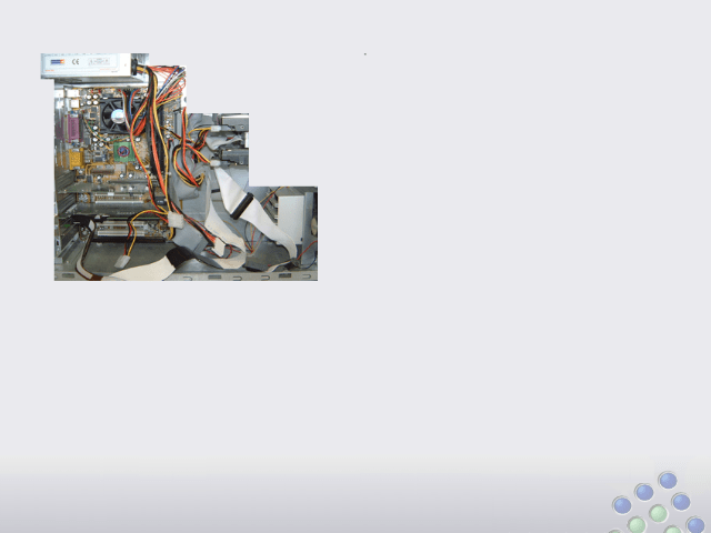
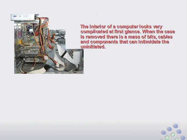
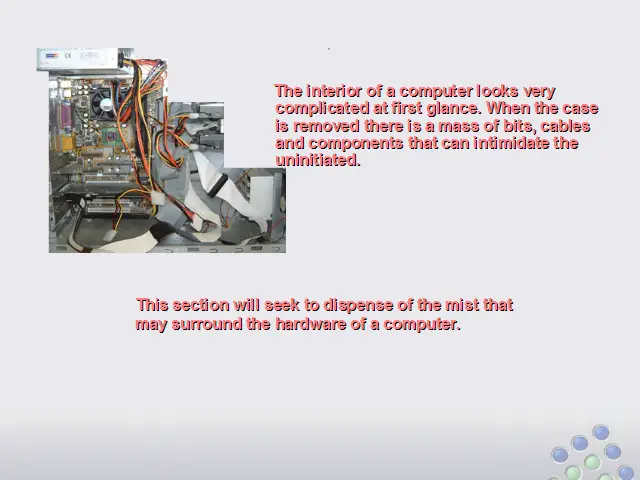
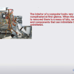
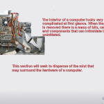
The interior of a computer looks very complicated at first glance. When the case is removed there is a mass of bits, cables and components that can intimidate the uninitiated. This lesson will seek to dispense some of the mist that may surround the hardware of a computer.
Use the buttons below to navigate through the lesson


Motherboards
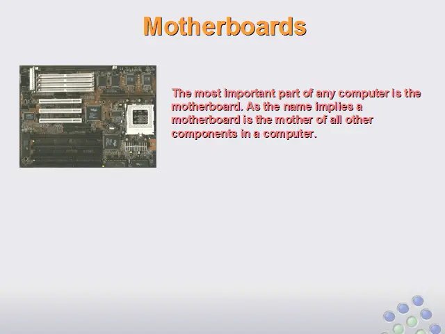
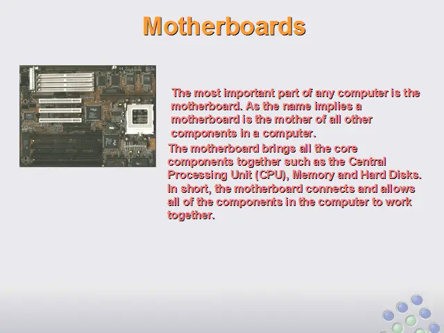
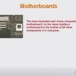
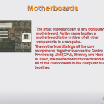
The most important part of any computer is the motherboard. As the name implies a motherboard is the mother of all other components in a computer.
The motherboard brings all the core components together such as the Central Processing Unit (CPU), Memory and Hard Disks. In short, the motherboard connects and allows all of the components in the computer to work together.
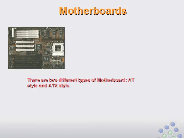
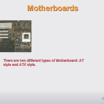
There are two different types of Motherboard: AT style and ATX style.
AT Motherboards
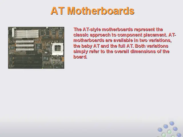
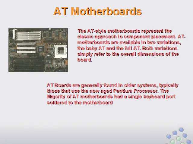
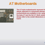
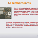
The AT-style motherboards represent the classic approach to component placement. AT-motherboards are available in two variations, the baby AT and the full AT. Both variations simply refer to the overall dimensions of the board.
AT Boards are generally found in older systems, typically those that use the now aged Pentium Processor. The Majority of AT motherboards had a single keyboard port soldered to the motherboard
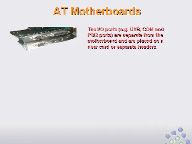
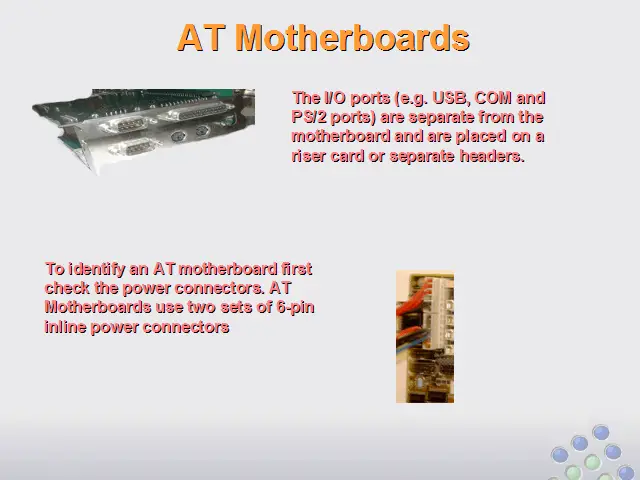
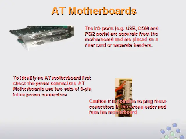
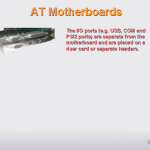
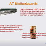
The I/O ports (e.g. USB, COM and PS/2 ports) are separate from the motherboard and are placed on a riser card or separate headers.
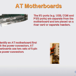
To identify an AT motherboard first check the power connectors. AT Motherboards use two sets of 6-pin inline power connectors
Caution it is possible to plug these connectors in the wrong order and fuse the motherboard
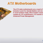
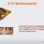
ATX Motherboards
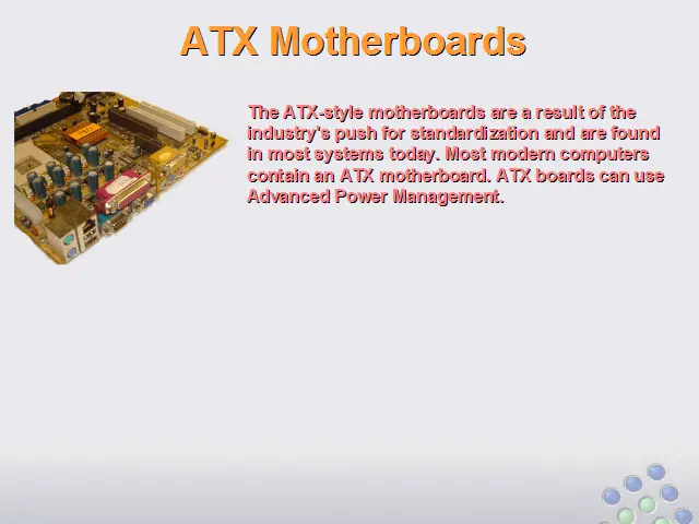
The ATX-style motherboards are a result of the industry’s push for standardization and are found in most systems today. Most modern computers contain an ATX motherboard. ATX boards can use Advanced Power Management.
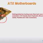
Distinguished by having more than just one external connector ATX boards have Keyboard, Mouse, Serial, Parallel and USB connectors.
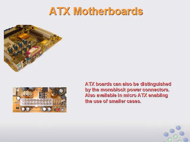
ATX boards can also be distinguished by the monoblock power connectors. Also available in micro ATX enabling the use of smaller cases.
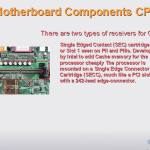
Motherboard Components
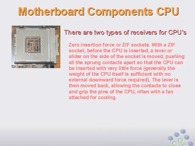
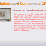
There are two types of receivers for CPU’s
Zero insertion force or ZIF sockets. With a ZIF socket, before the CPU is inserted, a lever or slider on the side of the socket is moved, pushing all the sprung contacts apart so that the CPU can be inserted with very little force (generally the weight of the CPU itself is sufficient with no external downward force required). The lever is then moved back, allowing the contacts to close and grip the pins of the CPU, often with a fan attached for cooling.
Single Edged Contact (SEC) cartridge slot or Slot 1 seen on PII and PIIIs. Developed by Intel to add Cache memory for the processor cheaply. The processor is mounted on a Single Edge Connector Cartridge (SECC), much like a PCI slot, but with a 242-lead edge-connector.
Bridges
There are two main bridges on a motherboard the Northbridge and the Southbridge. Bridges control access to the processor from the peripherals.
The Northbridge, also known as the Memory Controller Hub (MCH), is traditionally one of the two chips in the core logic chipset on a PC motherboard. The Northbridge typically controls communications between the CPU, RAM, AGP or PCI Express, and the Southbridge.. A Northbridge will typically work with only one or two classes of CPUs and generally only one type of RAM. There are a few chipsets that support two types of RAM (generally these are available when there is a shift to a new standard).
The Southbridge, also known as the I/O Controller Hub (ICH), is a chip that implements the “slower” capabilities of the motherboard in a Northbridge Southbridge chipset computer architecture. The Southbridge can usually be distinguished from the Northbridge by not being directly connected to the CPU. Rather, the Northbridge ties the Southbridge to the CPU. The functionality found on a contemporary Southbridge includes:PCI bus, ISA bus, SMBus, DMA controller, Interrupt controller, IDE, (SATA or PATA) controller ,LPC Bridge, Real Time Clock, Power management (APM and ACPI) and Nonvolatile BIOS memory
BIOS Chips
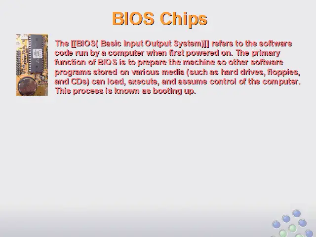
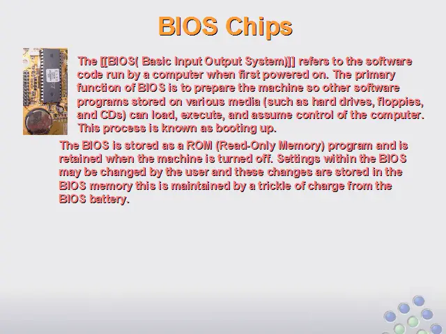
The [[BIOS( Basic Input Output System)]] refers to the software code run by a computer when first powered on. The primary function of BIOS is to prepare the machine so other software programs stored on various media (such as hard drives, floppies, and CDs) can load, execute, and assume control of the computer. This process is known as booting up.
The BIOS is stored as a ROM (Read-Only Memory) program and is retained when the machine is turned off. Settings within the BIOS may be changed by the user and these changes are stored in the BIOS memory this is maintained by a trickle of charge from the BIOS battery.
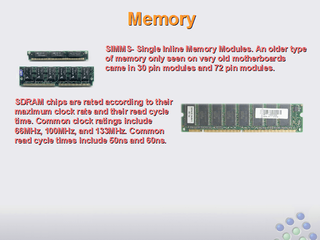
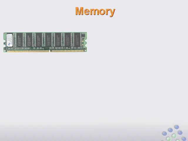
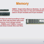
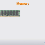
Memory
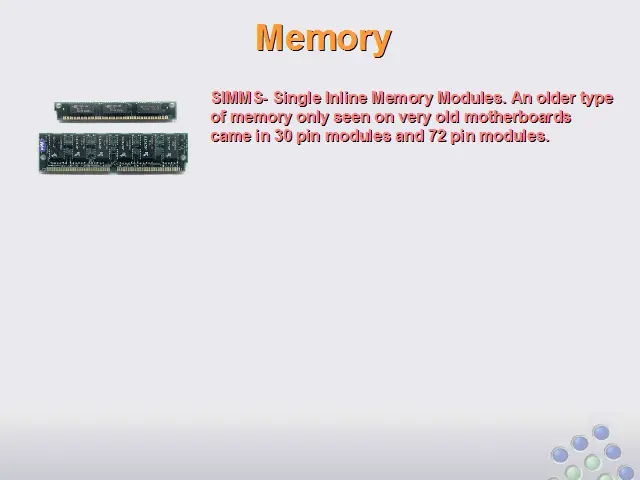
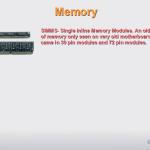
SIMMS- Single Inline Memory Modules. An older type of memory only seen on very old motherboards came in 30 pin modules and 72 pin modules.
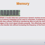
SDRAM chips are rated according to their maximum clock rate and their read cycle time. Common clock ratings include 66MHz, 100MHz, and 133MHz. Common read cycle times include 50ns and 60ns.
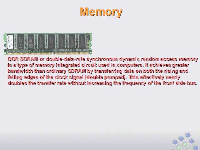
DDR SDRAM or double-data-rate synchronous dynamic random access memory is a type of memory integrated circuit used in computers. It achieves greater bandwidth than ordinary SDRAM by transferring data on both the rising and falling edges of the clock signal (double pumped). This effectively nearly doubles the transfer rate without increasing the frequency of the front side bus.
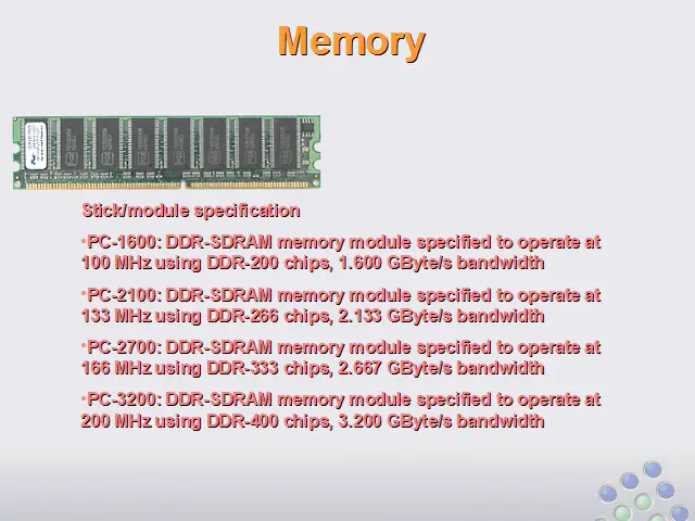
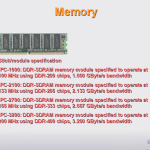
Stick/module specification
PC-1600: DDR-SDRAM memory module specified to operate at 100 MHz using DDR-200 chips, 1.600 GByte/s bandwidth
PC-2100: DDR-SDRAM memory module specified to operate at 133 MHz using DDR-266 chips, 2.133 GByte/s bandwidth
PC-2700: DDR-SDRAM memory module specified to operate at 166 MHz using DDR-333 chips, 2.667 GByte/s bandwidth
PC-3200: DDR-SDRAM memory module specified to operate at 200 MHz using DDR-400 chips, 3.200 GByte/s bandwidth
Drive Connectors
Integrated Device Electronic (IDE)
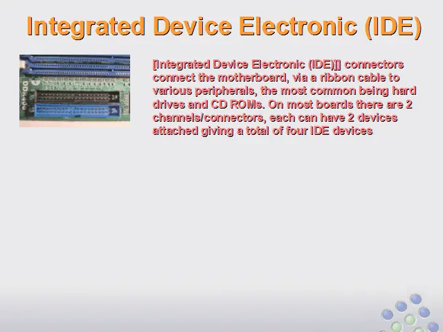
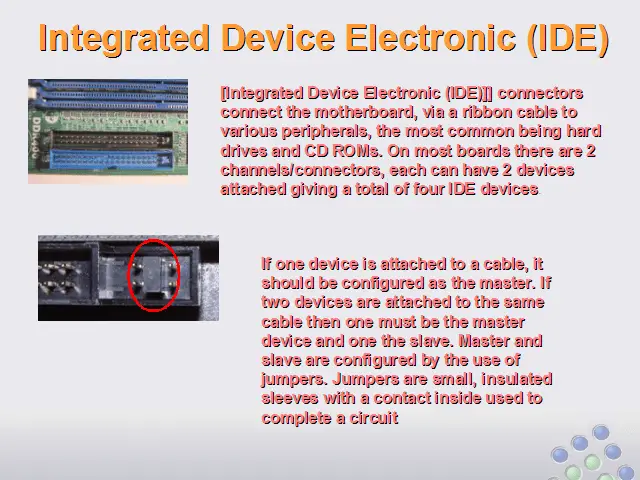
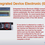
[Integrated Device Electronic (IDE)]] connectors connect the motherboard, via a ribbon cable to various peripherals, the most common being hard drives and CD ROMs. On most boards there are 2 channels/connectors, each can have 2 devices attached giving a total of four IDE devices.
If one device is attached to a cable, it should be configured as the master. If two devices are attached to the same cable then one must be the master device and one the slave. Master and slave are configured by the use of jumpers. Jumpers are small, insulated sleeves with a contact inside used to complete a circuit
Hard Disks
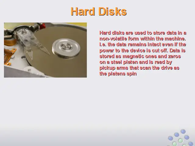
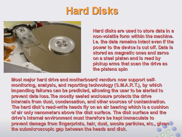
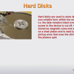
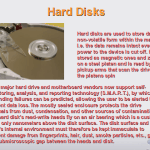
Hard disks are used to store data in a non-volatile form within the machine. I.e. the data remains intact even if the power to the device is cut off. Data is stored as magnetic ones and zeros on a steel platen and is read by pickup arms that scan the drive as the platens spin
Most major hard drive and motherboard vendors now support self-monitoring, analysis, and reporting technology (S.M.A.R.T.), by which impending failures can be predicted, allowing the user to be alerted to prevent data loss.The mostly sealed enclosure protects the drive internals from dust, condensation, and other sources of contamination. The hard disk’s read-write heads fly on an air bearing which is a cushion of air only nanometers above the disk surface. The disk surface and the drive’s internal environment must therefore be kept immaculate to prevent damage from fingerprints, hair, dust, smoke particles, etc., given the submicroscopic gap between the heads and disk.
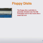
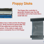
Floppy Disks
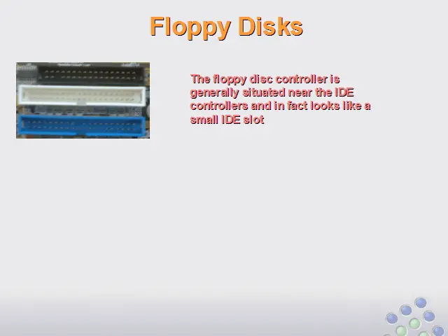
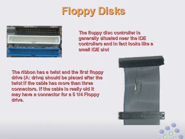
The floppy disc controller is generally situated near the IDE controllers and in fact looks like a small IDE slot
The ribbon has a twist and the first floppy drive (A: drive) should be placed after the twist if the cable has more than three connectors. If the cable is really old it may have a connector for a 5 1/4 Floppy drive.
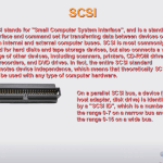
SCSI
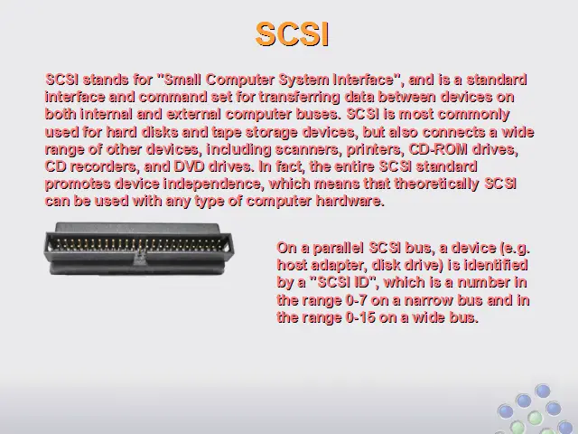
SCSI stands for “Small Computer System Interface”, and is a standard interface and command set for transferring data between devices on both internal and external computer buses. SCSI is most commonly used for hard disks and tape storage devices, but also connects a wide range of other devices, including scanners, printers, CD-ROM drives, CD recorders, and DVD drives. In fact, the entire SCSI standard promotes device independence, which means that theoretically SCSI can be used with any type of computer hardware.
On a parallel SCSI bus, a device (e.g. host adapter, disk drive) is identified by a “SCSI ID”, which is a number in the range 0-7 on a narrow bus and in the range 0-15 on a wide bus.
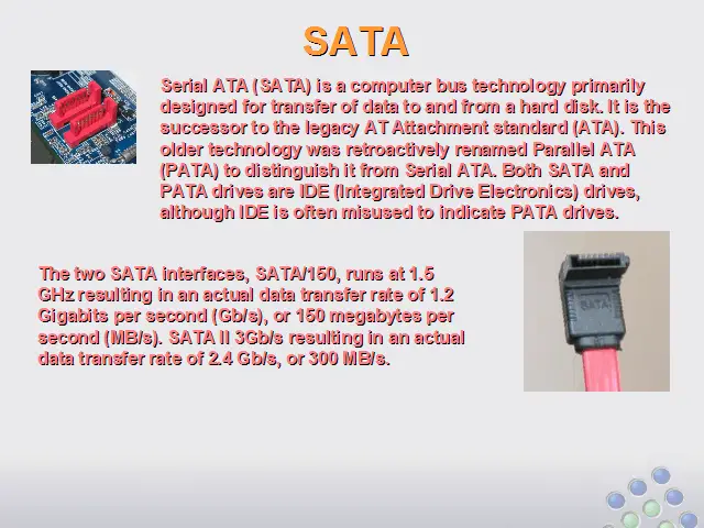
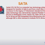
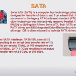
SATA
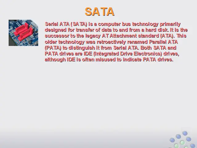
Serial ATA (SATA) is a computer bus technology primarily designed for transfer of data to and from a hard disk. It is the successor to the legacy AT Attachment standard (ATA). This older technology was retroactively renamed Parallel ATA (PATA) to distinguish it from Serial ATA. Both SATA and PATA drives are IDE (Integrated Drive Electronics) drives, although IDE is often misused to indicate PATA drives.
The two SATA interfaces, SATA/150, runs at 1.5 GHz resulting in an actual data transfer rate of 1.2 Gigabits per second (Gb/s), or 150 megabytes per second (MB/s). SATA II 3Gb/s resulting in an actual data transfer rate of 2.4 Gb/s, or 300 MB/s.
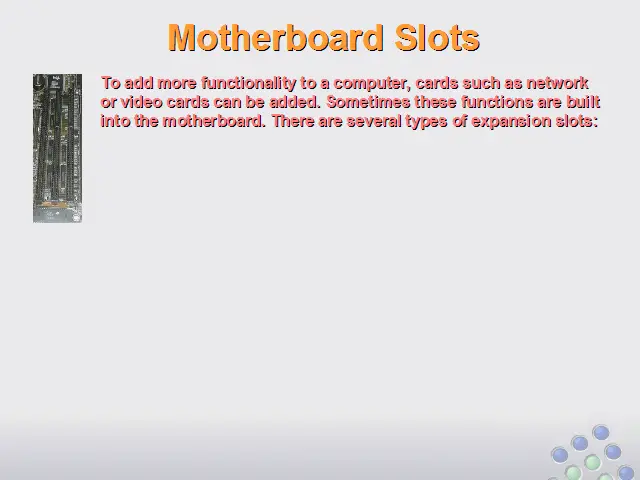
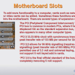
Motherboard Slots
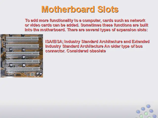
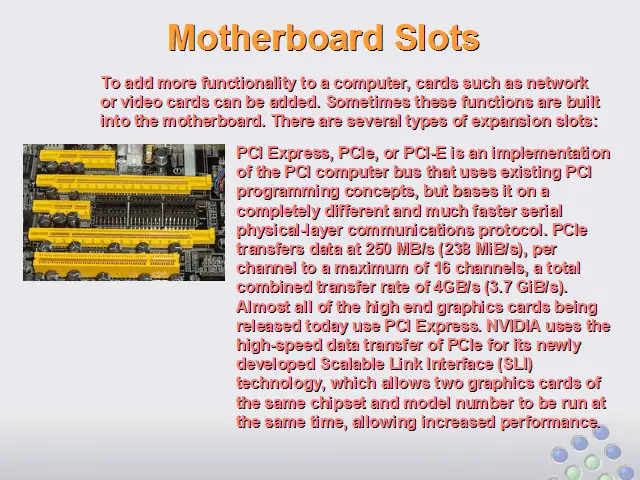
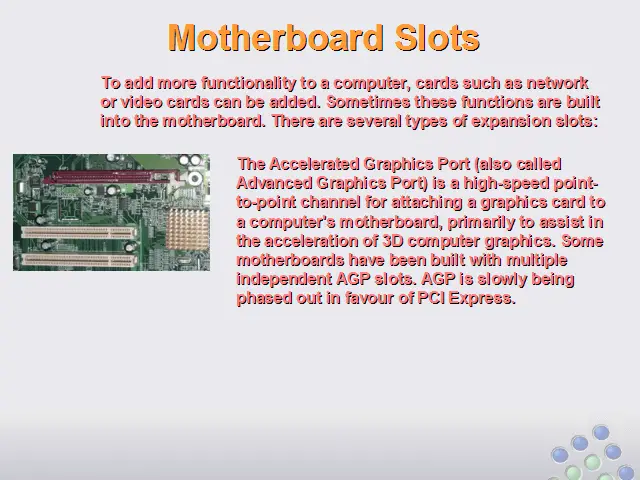
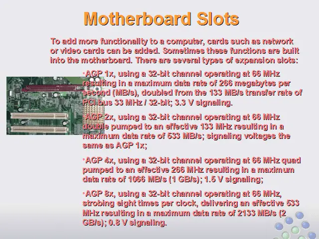
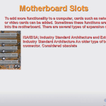
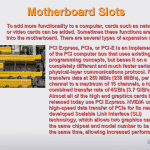
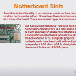
To add more functionality to a computer, cards such as network or video cards can be added. Sometimes these functions are built into the motherboard. There are several types of expansion slots:
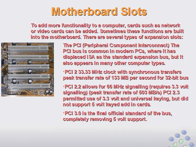
The PCI (Peripheral Component Interconnect) The PCI bus is common in modern PCs, where it has displaced ISA as the standard expansion bus, but it also appears in many other computer types.
PCI 2 33.33 MHz clock with synchronous transfers peak transfer rate of 133 MB per second for 32-bit bus
PCI 2.2 allows for 66 MHz signalling (requires 3.3 volt signalling) (peak transfer rate of 503 MB/s) PCI 2.3 permitted use of 3.3 volt and universal keying, but did not support 5 volt keyed add in cards.
PCI 3.0 is the final official standard of the bus, completely removing 5 volt support.
ISA/EISA; Industry Standard Architecture and Extended Industry Standard Architecture An older type of bus connector. Considered obsolete
PCI Express, PCIe, or PCI-E is an implementation of the PCI computer bus that uses existing PCI programming concepts, but bases it on a completely different and much faster serial physical-layer communications protocol. PCIe transfers data at 250 MB/s (238 MiB/s), per channel to a maximum of 16 channels, a total combined transfer rate of 4GB/s (3.7 GiB/s). Almost all of the high end graphics cards being released today use PCI Express. NVIDIA uses the high-speed data transfer of PCIe for its newly developed Scalable Link Interface (SLI) technology, which allows two graphics cards of the same chipset and model number to be run at the same time, allowing increased performance.
The Accelerated Graphics Port (also called Advanced Graphics Port) is a high-speed point-to-point channel for attaching a graphics card to a computer’s motherboard, primarily to assist in the acceleration of 3D computer graphics. Some motherboards have been built with multiple independent AGP slots. AGP is slowly being phased out in favour of PCI Express.
AGP 1x, using a 32-bit channel operating at 66 MHz resulting in a maximum data rate of 266 megabytes per second (MB/s), doubled from the 133 MB/s transfer rate of PCI bus 33 MHz / 32-bit; 3.3 V signaling.
AGP 2x, using a 32-bit channel operating at 66 MHz double pumped to an effective 133 MHz resulting in a maximum data rate of 533 MB/s; signaling voltages the same as AGP 1x;
AGP 4x, using a 32-bit channel operating at 66 MHz quad pumped to an effective 266 MHz resulting in a maximum data rate of 1066 MB/s (1 GB/s); 1.5 V signaling;
AGP 8x, using a 32-bit channel operating at 66 MHz, strobing eight times per clock, delivering an effective 533 MHz resulting in a maximum data rate of 2133 MB/s (2 GB/s); 0.8 V signaling.
Peripheral Connections
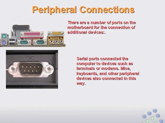
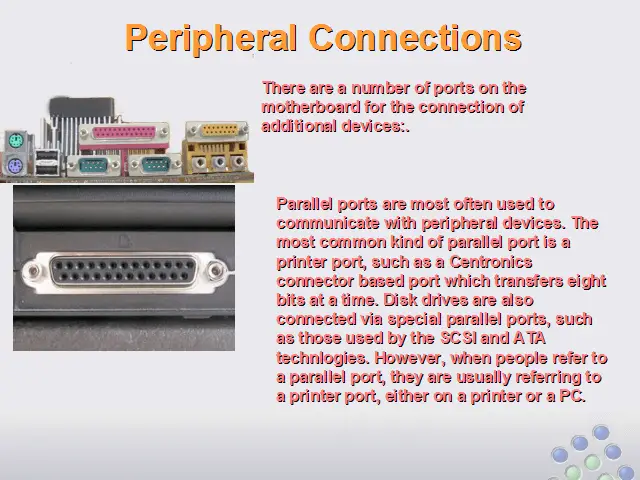
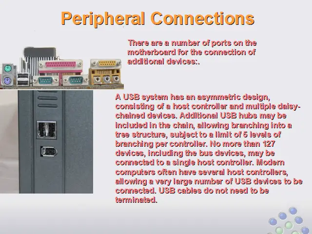
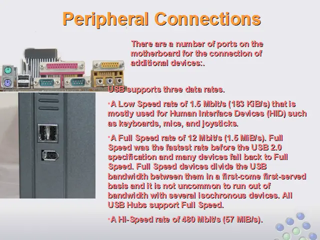
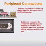
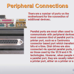
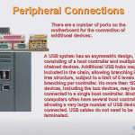
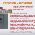
There are a number of ports on the motherboard for the connection of additional devices:.
Serial ports connected the computer to devices such as terminals or modems. Mice, keyboards, and other peripheral devices also connected in this way.
Parallel ports are most often used to communicate with peripheral devices. The most common kind of parallel port is a printer port, such as a Centronics connector based port which transfers eight bits at a time. Disk drives are also connected via special parallel ports, such as those used by the SCSI and ATA technlogies. However, when people refer to a parallel port, they are usually referring to a printer port, either on a printer or a PC.
A USB system has an asymmetric design, consisting of a host controller and multiple daisy-chained devices. Additional USB hubs may be included in the chain, allowing branching into a tree structure, subject to a limit of 5 levels of branching per controller. No more than 127 devices, including the bus devices, may be connected to a single host controller. Modern computers often have several host controllers, allowing a very large number of USB devices to be connected. USB cables do not need to be terminated.
USB supports three data rates.
A Low Speed rate of 1.5 Mbit/s (183 KiB/s) that is mostly used for Human Interface Devices (HID) such as keyboards, mice, and joysticks.
A Full Speed rate of 12 Mbit/s (1.5 MiB/s). Full Speed was the fastest rate before the USB 2.0 specification and many devices fall back to Full Speed. Full Speed devices divide the USB bandwidth between them in a first-come first-served basis and it is not uncommon to run out of bandwidth with several isochronous devices. All USB Hubs support Full Speed.
A Hi-Speed rate of 480 Mbit/s (57 MiB/s).